Reactive Power Vector Diagram Diagram Of Reactive-power-cont
Reactive inverter apparent pv factor What is active and reactive power and what are the difference between Power reactive compensation control voltage apparent real tonex line shunt training
Reactive power variations against simulation time Figure 17 represent
Vector diagram while supplying reactive power. Reactive power concept Reactive power under different scenarios
Power reactive active ac calculate voltage triangle not real complex rated current source capacitor electronics circuit ws tutorials why engine
What is reactive power?Reactive power negative active never Ac – understanding reactive power in ac circuit – valuable tech notesReactive power.
Reactive power ppt voltage control powerpoint presentation phaseActive/reactive power with proposed method in [24]. Reactive power control diagramReactive power vector svg icon.

Active, reactive, apparent and complex power. explanation & formulas
Power reactive shifting phase active factor through need janitza electrical fig transmission maintain deliver voltage watts ars required linesReactive power variations against simulation time figure 17 represent Reactive power – voltage correlationReactive power apparent active electrical complex formulas ac real explanation calculate current engineering true voltage simple between triangle actual watt.
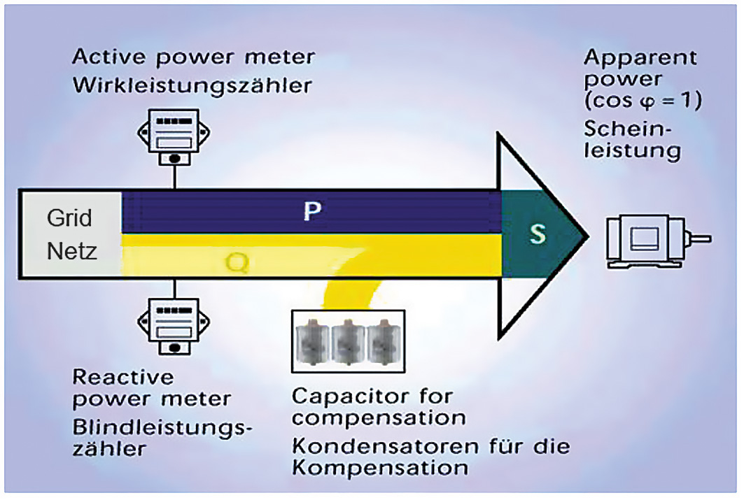
Reactive power compensation – learnchannel-tv.comReactive power consumed by the generator. Avr siemens connection diagram possible trouble with reactive powerPower factor correction.

Reactive power compensation of reactive components
Diagram of reactive-power-control part.Reactive power and the need of reactive power ~ how electrical Reactive powerReactive power.
Concept of reactive powerReactive power variations of system under consideration Reactive power compensation and voltage controlReactive power control.

Output reactive power of svg system under constant reactive power
Compensation learnchannel reactiveReactive power and its impact on the grid Reactive power compensation diagram circuit equivalent calculations loading network example block shows figureActive and reactive power vector control system of dfig.
Active-reactive power plane for a single-phase pv inverter. theReactive power Power reactive apparent equations true reactance factor ac impedance active using circuit circuits resistance electric complete description three refReactive power and voltage control strategy.

Reactive power control model (voltage-reactive power characteristic
Impact of reactive power on the voltage profile. case 2, without4 example calculations of compensation for reactive power .
.


Active-Reactive Power Plane for a single-phase PV inverter. The

Reactive power and voltage control strategy | Download Scientific Diagram

Diagram of reactive-power-control part. | Download Scientific Diagram

AC – Understanding Reactive Power in AC Circuit – Valuable Tech Notes

Reactive power variations against simulation time Figure 17 represent
REACTIVE POWER AND THE NEED OF REACTIVE POWER ~ HOW ELECTRICAL

Active, Reactive, Apparent and Complex Power. Explanation & Formulas